Vibration Analysis
Following subtopics are derived from the whitepaper by ST on predictive maintenance.
Related links
Other references
- Note on Vibration analysis from pumpandsystems.com
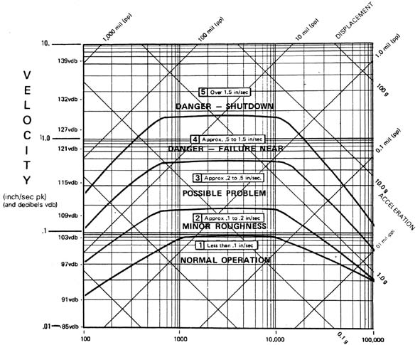
- ST documents
Competitors
- AssetWatch
- They were funded by g2vp
- Augury
- nanoprecise
- kcftech
Ideas
- Calculate FFT for individual CEEMDAN components to get the clean frequency and amplitudes out.
- Explore the value of RMS (3-components together) analysis
- Explore PCA
Time domain analysis
They estimate both acceleration and speed through the accelerometer readings.
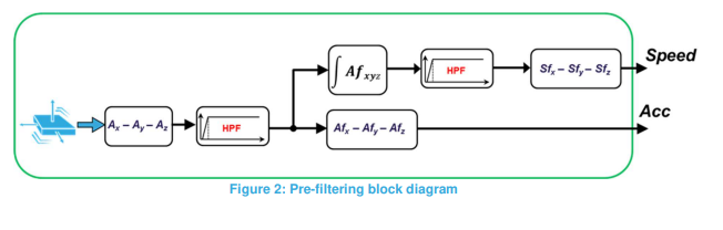
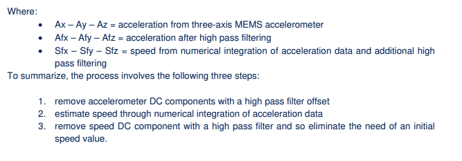
- Should we derive speed as a parameter?
- For now we don't
- We want to consider whether to implement a high pass filter.See if we already have a HPF in the accelerometer itself and if we are utilizing it?
- Multiple settings for sampling (0.5G, 1G, 2G, etc.) based on the maximum frequency we need to capture.
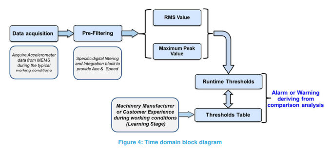
Then for both or either from acceleration and speed, peak and RMS values should be calculated and alarm conditions need to be defined based on value thresholds.
Frequency domain analysis
FFT is calculated on either acceleration or speed.
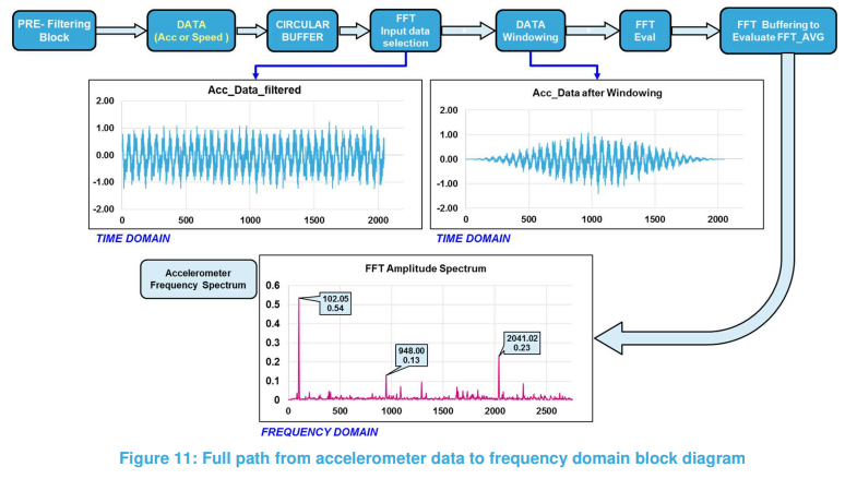
Dataflow of ST FFT calculation
- Loading data into a
circular buffer - Appropriate windowing
- Averaging with or without overlapping
- Calculate FFT and buffer the result to calculate AVG. A
dual buffermethod can be used where the secondary buffer is used to hold the data for FFT calculation where as the primarycircular buffercan be filled with real-time accelerometer data
- Loading data into a
On a low priority test the implication of FFT averaging using the simulation setup. If it yields better results, we should update the DeepVibe setup to send
nx 1024 samples by sendingnpackets for each measurement cycle for appropriate value ofn.Shall we implement all these in ESP32 itself?
- Sudhir: No
Analyze FFT spectrum
Define the alarm threshold values based on frequency bands.
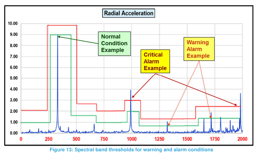
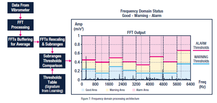
If above can be implemented on ESP32, analysis can also be done on ESP32 side. Thresholds can be defined as three arrays for
normal,warning, andcriticalconditions.- Sudhir: No FFT implementation of ESP32
If we plan to have
Grafana alertssent out on these conditions, we can use the following approach.- Sudhir: No. We are not going to use Grafana for setting these up
- Define the thresholds as arrays in the
C applicationwhere we calculate FFT. - Create alerts table for each node in TDEngine. Need to define the structure.
- Grafana will send alerts based on the content in
alerts tablein TDEngine DB.
Try standalone Python application (Implement the thresholds)
- define the thresholds for 500Hz buckets
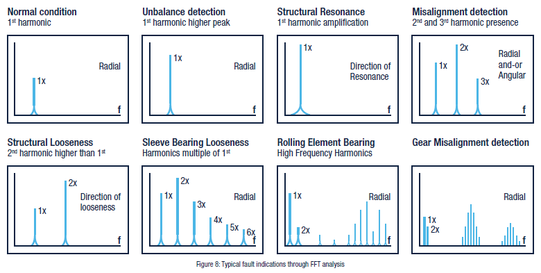
- How to implement Figure 8?
How do we tune the alarm thresholds for our application?
Python based FFT alert condition generation test
This colab notebook is used for the experiment.
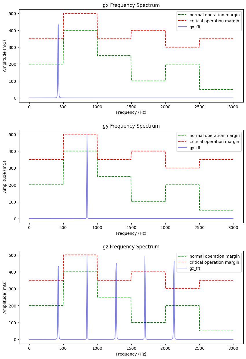
A 425Hz sinusoidal with an amplitude of 500 mG is generated as main time-domain signal. They are transmitted as following under each axis.
gx: primary component of the signalgy: 2nd harmonic of the signalgx: primary + 4 harmonics of the signal
FFT result and the dummy condition thresholds are shown in the following graphs.
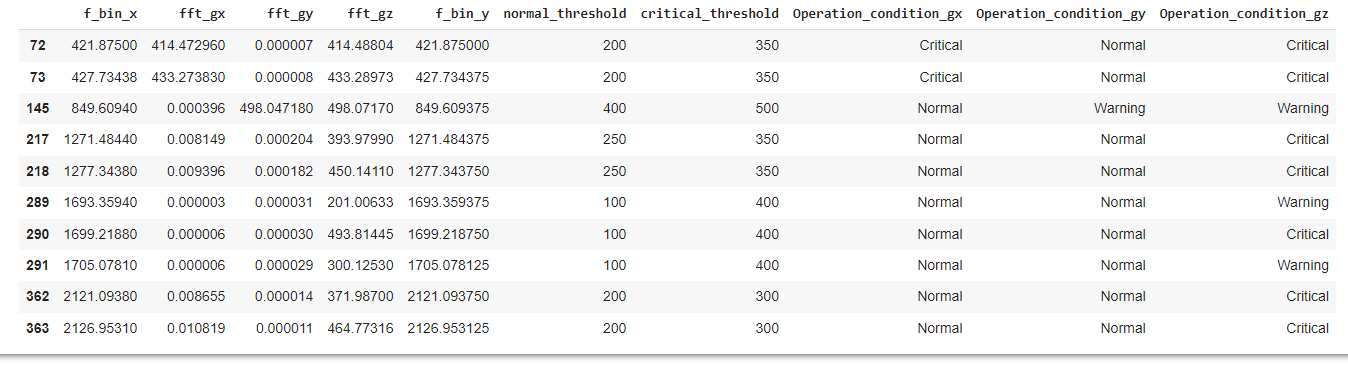
Based on the thresholds, three condition labels, Normal, Warning, and Critical, are assigned for each frequency bin. Following is a filtered result for Warning and Critical statuses on all axises.
We can modify this workflow to send out alerts, save the operation condition data, and more.