Design Document
June 06, 2023 (Update 2)
New algorithm
Based on the findings below, the final logic is updated to this. When we start the seed counting routine for envelope 1, the following algorithm with the boolean variable,
skip the current chuteset toFalseand while moving to all other envelopes the algorithm is called withskip the current chuteset toTrue
- If the boolean switch to skip the current chute is set, rotate the plate by 48 degrees.
- Plate starts to rotate from
state 1in 6 degree steps. Sensor state is checked after each step.-d7952ae673e3401d0a157ca641b6099a.png)
- Once the sensor goes
HIGH, the plate has reachedstate 2. It will then move back in 1 degree steps.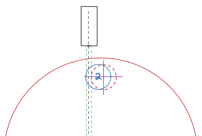
- Once the sensor goes
LOW, the plate has reachedstate 3. It has found the right edge of the chute.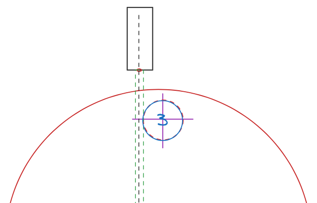
Results: video link
ToDo
- Test this between several runs
- Test the operation with 10 consecutive runs I tested the carousal alignment with 10 runs, and it managed to align with the chute with every turn it made. But the number of forward and backward movements it had to do with different chutes were different ( I suspect it should have to do with the reflectivity or some other mechanical parameter which changes between the chutes affects the mechanism. And there is a small play of few degrees in the rotary plate which I can feel by hand)
- Test the operation with random different starting positions of the rotary plate. Different starting positions will be introduced by a test code which rotates the rotary plate by random angles at the start. Tested around 20 times, the logic was able to find and align with the first chute and go through the seed counting cycle as expected every time.
- See how we can get a feedback from the motor after it complete an instructed motion.
June 06, 2023
Proposed test for addressing the issue recorded on **May 30, 2023 (Update 2)
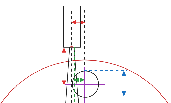
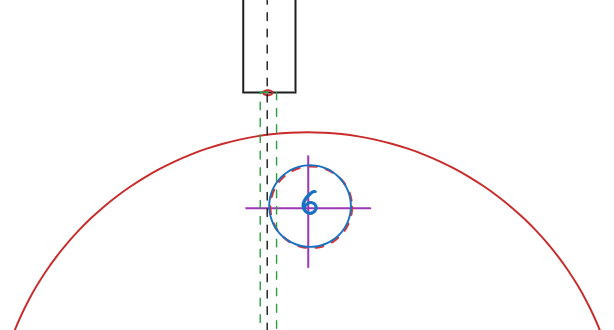
Placement of the chute, drop hole and the sensor is as shown in the following diagram. We only know that the left sensor is placed to the left side of the drop hole and uncertain about the exact offset values.
Modified algorithm
- Plate starts to rotate from
state 1in 6 degree steps. Sensor state is checked after each step.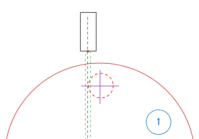
- Once the sensor goes
HIGH, the plate has reachedstate 2. It will then move back in 1 degree steps.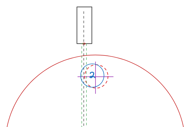
- Once the sensor goes
LOW, the plate has reachedstate 3. It has found the right edge of the chute.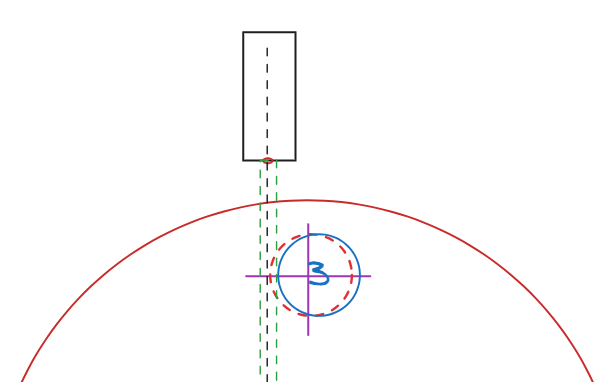
- Then the chute moves back to
state 2in a single step using the knowledge of the steps moved in #3. - Plate continue to move forward till
state 4, where the sensor goesLOWagain. It has found the left edge of the chute.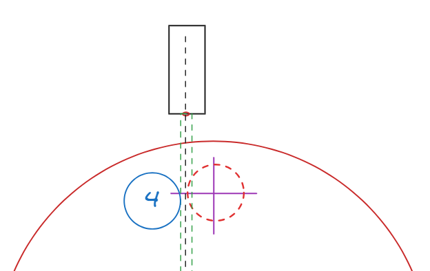
- Taking the number of steps moved from left edge to right edge of the chute into account, the plate is moved to the mid point which is
state 5and the chute center line is centered with the sensor center line.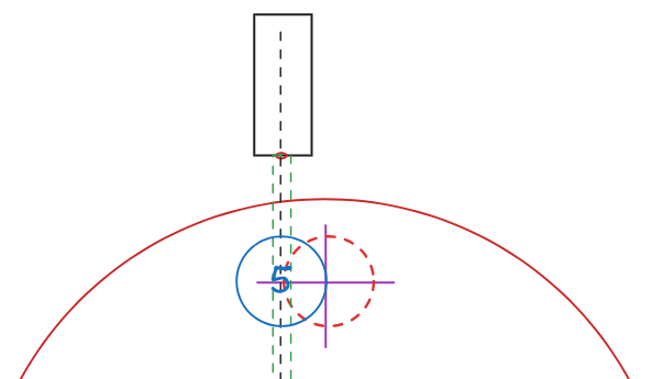
- Finally, we rotate the plate to right-hand side further by a fixed offset angle which will be fine-tuned by observation, to account for the horizontal offset between the sensor center line and the actual drop hole marked in dashes.
Tasks
- Implement this algorithm
- Fine tune the fixed offset angle
- Found the fixed offset angle to be 12.5 degrees.
- Alignment still fails at places where we have the fastner heads inline with the sensor.
- Observed that
state 3seems to be same asstate 6. Will test this further. If the two states are equivalent, we can trim the algorithm to just reachstate 3.
- Test with a trimmed down algorithm to reach
state 3only.- Works as expected.
State 3is chute aligned position (Need to verify the positioning of chute and sensors are same between units so this can be reproducible)
- Works as expected.
- Increased the speed of the alignment by taking a large step of 48 degrees when jumping between envelopes.
- 48 degrees = 45 degrees (angle between chutes) + 3 degrees (additional few degrees to ensure we land on the next chute by this rotation)
Result: video link
May 30, 2023 (Update 2)
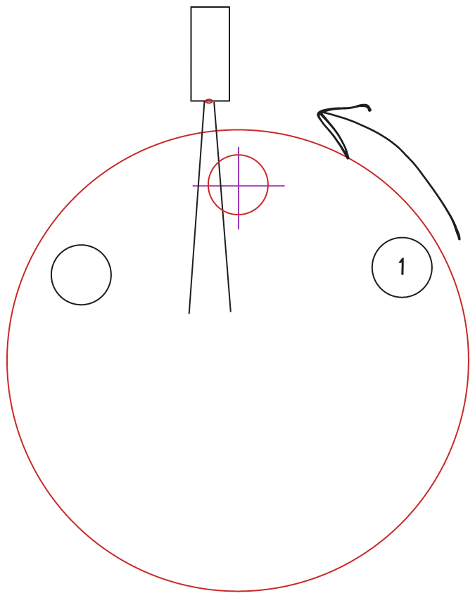
Test further to see failure points in the current logic, so we can address them as well. Upon further checking I had a suspicion about the sensor placement. With the logic we had in place, it moves the chute to the center of the sensor correctly as observed from beneath. I tried dropping few peanuts from the top basin and some seems to be getting stuck. Since it was not as expected, I dissembled the top portion of the carousal and found that our fundamental assumption of the sensor being placed aligning with the drop hole from the top is wrong. Sensor is placed slightly away from the center as below ( I assume they wanted to align the sensor field of view with the edge of the chute instead of the center). It is hard to say if the sensor is mounted to be aligned with the edge of the chute or not. Should we ask Alan on how the design was made?
May 30, 2023
Visual representation
Here is a visual representation of the current chute alignment method. Different positions of the chute corresponds to different states of the system.
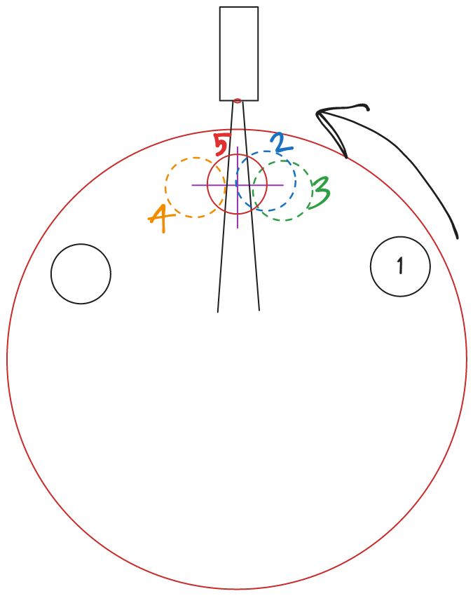
- Plate starts to rotate from
state 1in 6 degree steps. Sensor state is checked after each step. - Once the sensor goes
HIGH, the plate has reachedstate 2. It will then move back in 1 degree steps. - Once the sensor goes
LOW, the plate has reachedstate 3. It has found the right edge of the chute. - Then the chute moves back to
state 2in a single step using the knowledge of the steps moved in #3. - Plate continue to move forward till
state 4, where the sensor goesLOWagain. It has found the left edge of the chute. - Taking the number of steps moved from left edge to right edge of the chute into account, the plate is moved to the mid point which is
state 5and the alignment is complete.
After filling in an envelope, the plate is turned forward till the sensor goes
LOWagain and the above logic is applied to align with the next chute.
Next steps
- Time (using a physical stopwatch) the motor movements for different degrees to identify a relationship between the rotation time vs. degrees to move,
- 1 degree
- 6 degrees
- 45 degrees
- 360 degrees
- As an alternative method, measure how off it will go if we start to move the plate by fixed number of degrees (Calculated by counting the steps between two consecutive chutes) after initial alignment.
- Seems it does not go off between runs
May 19, 2023
This is related to the status update in this email
Planned items
- Thorough testing to see if there are more points of failure on chute alignment.
- Adjusting the time delays and the increment angles to a sweet spot to make the chute alignment faster without introducing errors.
new_FindNextChute()is the current logic used for aligning the chute. It is located inCounterScreen.ccfile.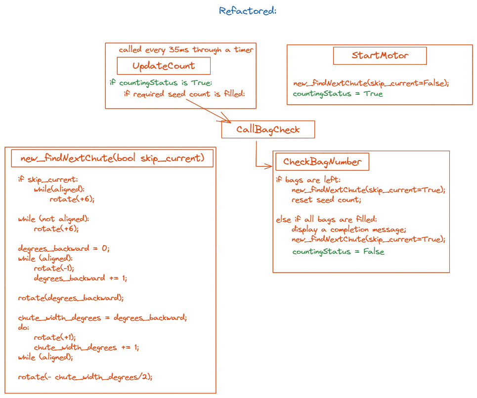
- After each motor rotate command R-Pi waits for
1+degrees of movement/2seconds. But for some of the steps the delay had to be increased further for the motor to work properly. These times need to be fine tuned to minimize the movement time. Delay times are implemented using the standard sleep function fromtime.h. - The function code should be refactored for easy parameter adjustments.
- The step sizes used in the code are 6 degrees (for large steps) and 1 degree (for small steps). Will explore to what extent we can increase these two to obtain faster and finer control.
- Modify or change the chute alignment logic if we can improve the efficiency.
- In the current code, we do not get feedback from the motor to know when the motor has completed an instructed move. Instead, we wait for a fixed amount of time in the R-Pi. To fine tune and increase the speed of the carousal logic, I will find if we are able to get feedback from the motor and implement motor control based on that.
- As a better alternative to the delay time adjustment in the point above, this will be explored so the machine will be more robust against any disturbances.